Pressure relief valves have been around for centuries, serving as the last line of defense to protect life and property in the event of overpressure incidents.
Introduction to Pressure Relief Valves: A Historical Perspective
A Pressure Relief Valve (PRV) is a term used to describe a type of valve designed for overpressure protection applications. You may have heard various terms for PRVs: Safety Valve, Relief Valve, Safety Relief Valve, or Pilot Operated Safety Relief Valve. While their operation is similar, there are nuances. Like any other type of equipment, everything seems the same from the outside. Still, as you delve into the details, you’ll discover the differences. So, let’s dive in, starting with some terms and definitions, then delve into the operation of a spring-loaded safety relief valve.
Types of Pressure Relief Valves: Definitions and Functions
Pressure Relief Valve (PRV) – A device designed to open and release excess pressure, then close to prevent further flow of fluid after normal conditions have been restored.
Relief Valve (RV) – A spring-loaded pressure relief valve driven by upstream static pressure. Relief valves are mainly used for incompressible fluids.
Safety Relief Valve (SRV) – A spring-loaded pressure relief valve, used as a safety valve or pressure relief valve depending on the application.
Pilot Operated Safety Relief Valve (POSRV) – A relief valve where the main pressure relief device or main valve is combined with an automatic auxiliary relief valve called a pilot valve and controlled by it.
Safety Valve (SV) – A spring-loaded pressure relief valve driven by upstream static pressure, known for rapid opening or popping. Safety valves are typically used for compressible fluids, primarily steam.
Now, let’s delve into the topic of this text, which is the operational basics of the spring-loaded safety relief valve (SRV)
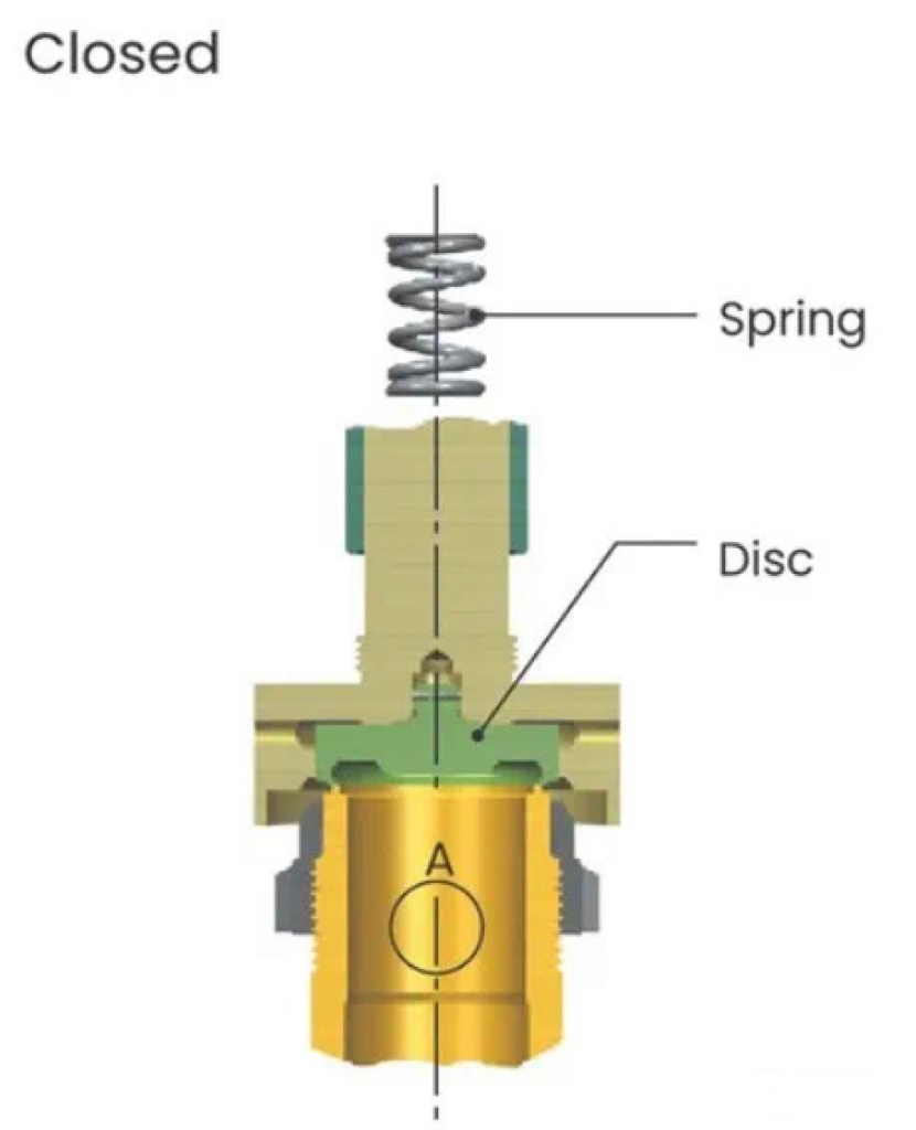
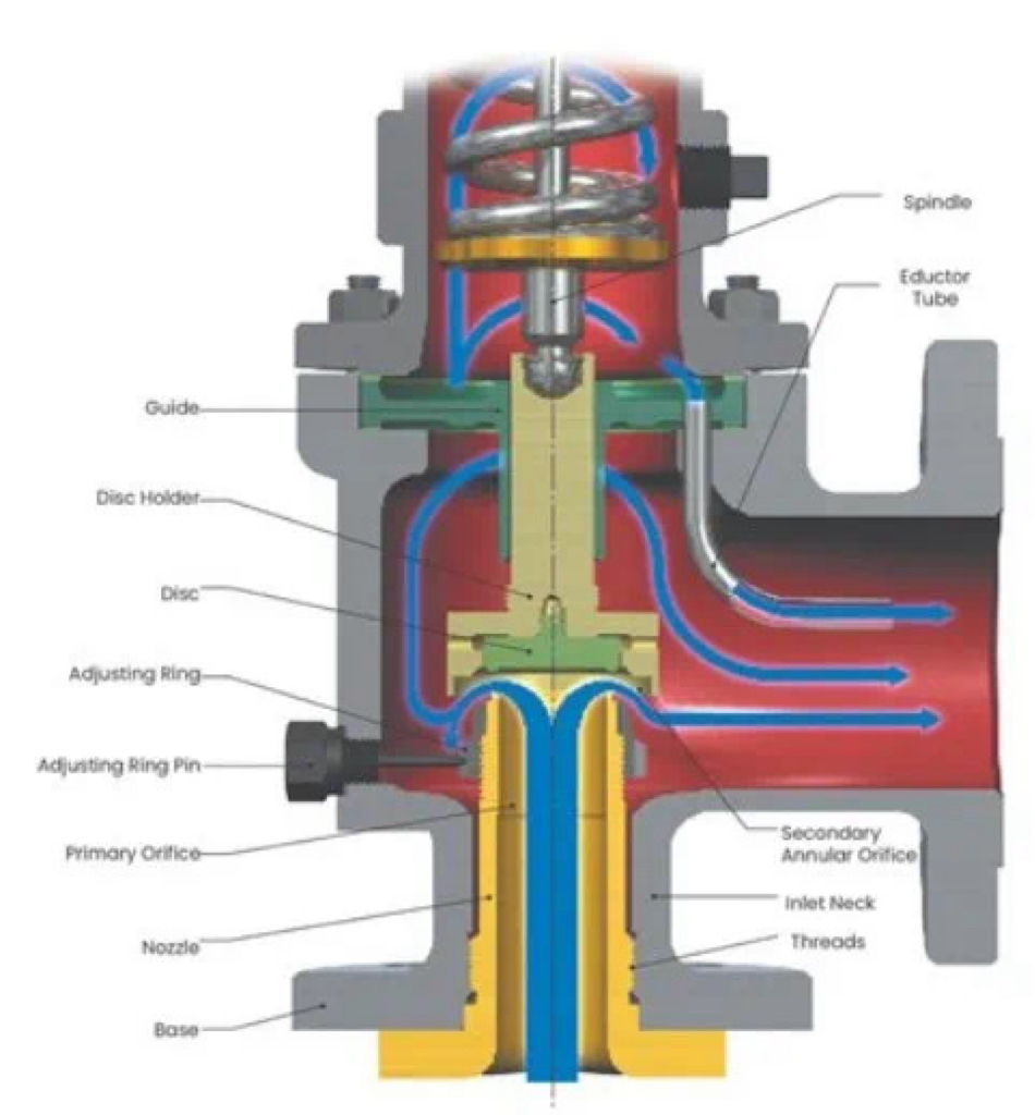
The spring-loaded relief valve SRV consists of an inlet nozzle connected to the container or system to be protected, a valve disc that moves to control the flow through the nozzle, and a spring that controls the valve opening time and disc position. The valve opens to release the specified capacity by using the system pressure to overcome the spring load. As shown in Figure 1, when the valve is closed, the spring force acts on the upstream pressure on the valve seat surface (Area A). As the pressure increases, the pressure at (A) tends to balance the spring force, keeping the valve seat together under pressure close to zero.
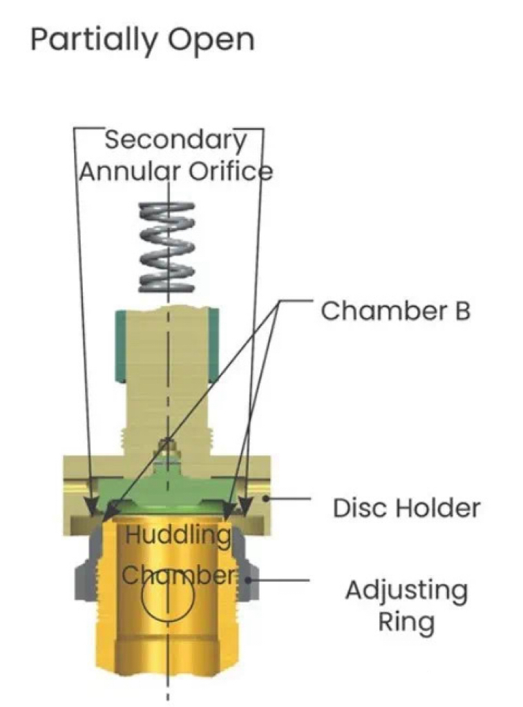
When the upstream pressure increases to within 1% to 2% of the set pressure of the valve, the medium will enter chamber B through the valve seat surface. The flow restriction at the secondary annular orifice causes an increase in pressure, acting on a larger area, generating additional force to overcome the spring force. The valve disc will then leave the nozzle seat, and the valve will ‘pop’ open.
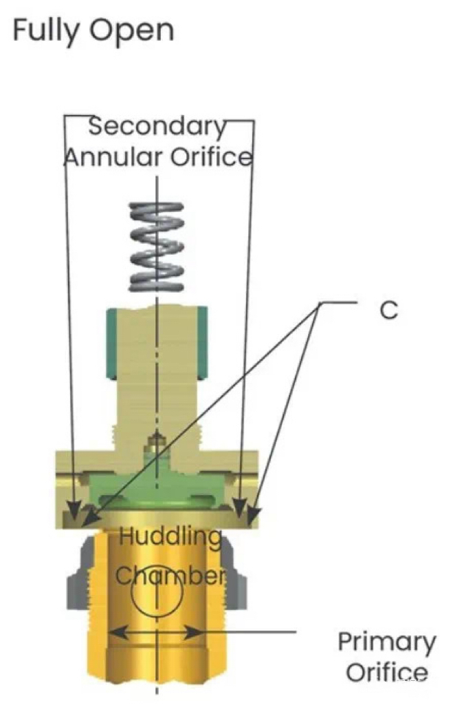
Once the valve is open, additional pressure builds up at point (C). This is a result of a sudden increase in flow and another annular orifice restriction formed between the inner edge of the valve disc retainer and the outer diameter of the adjusting ring. The additional forces at point (C) significantly elevate the valve disc during the “pop” event. Flow is restricted by the opening between the nozzle seat and the valve disc seat until the valve disc seat lifts approximately one-quarter of the nozzle throat diameter. After reaching this lift, the flow is restricted by the main throttling orifice rather than the area between the valve seat surfaces. By positioning a single adjusting ring, the blowdown (the difference between opening and closing pressures) can be controlled within a defined range. Pressure relief occurs when the combined forces at points (A), (B), and (C) exceed the spring force, continuing until the pressure at point (A) drops below the set pressure.
The diagram below depicts the fluid flowing through the valve. It’s crucial to recognize that system pressure enters through the nozzle, maintaining high pressure until it expands through the secondary annular orifice. The pressure downstream of the secondary annular orifice is significantly lower than the system pressure.
Features
Adjustment Ring
Before putting the safety relief valve into operation, set its adjustment ring to the predetermined position. Through presetting, there’s no need for the valve to pop open during usage, ensuring the ring is correctly positioned to achieve the necessary lift and pressure relief capacity.
Simple Blowdown Adjustment
An adjustment ring regulates the blowdown or reseating pressure in the safety relief valve. As the ring moves upward, the blowdown increases (reducing the valve seat reseating pressure), and as the ring moves downward, the blowdown decreases (raising the valve seat reseating pressure). In contrast, when the valve has two or more adjustment rings, each ring influences the valve’s action and blowdown.
Common Industries and Applications
Spring-loaded safety relief valves find applications in various industries, including power generation, refining, petrochemicals, chemical processing, midstream oil and gas, upstream oil and gas, pulp and paper. Common applications of spring-loaded safety relief valves include distillation, hydroprocessing, reforming, cracking, blending, fractionation, gas compression, separation, compression, pipeline integrity, dehydration, and factory balance applications for gas, liquid, and two-phase media.
The operational principles of spring-loaded safety relief valves are fundamentally simple, with only a few components controlling their functions. There’s much more to discuss about SRVs, such as internal types, operational nuances, and when to use specific trims. However, for now, we are focusing on the fundamental operational principles of SRVs.