Orifice flanges are components of orifice flow meters, appearing in pairs. They are used to detect the flow rate of liquids or gases within pipelines. Orifice flanges typically have two pressure tapping holes on the flange side, positioned opposite each other. With orifice flanges, there is no need to install a separate orifice plate carrier on the pipeline or create openings in the pipeline.
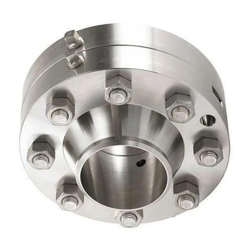
Orifice flanges are usually flat-faced or ring-joint, and, apart from additional machining, they generally match standard neck-welding flanges and flat-welding neck flanges. The diagram below shows a set of orifice flanges, with the orifice plate in the middle and lifting bolts on the flange. The lifting bolts are used to separate the flanges for inspection or replacement of the orifice plate and flange gasket.
The manufacturing and installation techniques of orifice flow meters are most commonly used in natural gas metering. They consist of a throttling device, impulse lines, differential pressure transmitter, pressure gauge, and thermometer, among others. Under normal circumstances, their measurement accuracy can meet the requirements of national standards and petroleum industry standards. However, in practical work, factors such as non-compliance with design, manufacturing, installation, and usage standards of the throttling device, improper parameter selection, fluctuations in user loads, and inaccurate manual readings can all affect the accuracy of flow measurement to varying degrees. The throttling device, also known as a differential pressure flow meter, is widely used for gas, steam, and liquid flow measurement. It is characterized by its simple structure, easy maintenance, and stable performance. Therefore, identifying the causes of measurement errors in orifice flow meters and finding solutions is crucial for ensuring accurate measurements.
Manufacturing and Installation of Orifice Plates
When using an orifice plate flow meter, the technical requirements for the fabrication of the orifice plate are stringent and must comply with national standards or relevant regulations; otherwise, it may introduce errors in natural gas flow measurements.
(1) Orifice Plate Eccentricity:
Experiments indicate that the measurement error caused by orifice plate eccentricity is generally within 2%. The impact of eccentricity increases with the higher value of the diameter ratio (β), so it is advisable to avoid using orifice plates with high β values.
(2) Orifice Plate Bending:
Improper installation or maintenance can lead to bending or deformation of the orifice plate, resulting in significant flow measurement errors. Testing on orifice plates used in flange pressure tapping revealed that the maximum error caused by orifice plate bending is approximately 3.5%.
(3) Protrusions in Throttling Devices:
Protrusions such as gaskets and welds extending into the pipe within the throttling device can introduce certain errors in flow measurement. The magnitude of the error depends on the position of the protrusion, the distance between the orifice plate and the protrusion, and the height of the protrusion. Experiments show that when β=0.7 and the protrusion is located 2 times the pipe diameter upstream of the orifice plate, the maximum error is produced. If the protrusion is located upstream of the orifice plate, the error ranges from 16% to 50%, while placing the protrusion downstream of the orifice plate results in a smaller impact on measurement accuracy.
To enhance measurement accuracy, the following measures can be taken:
(1) Pipeline Requirements:
Ensure that the dimensions, straight pipe sections, roundness, and internal surface roughness of the measuring pipe comply with the strict technical requirements of national standards. If the minimum length of the measuring pipe does not meet the standard requirements, it may result in deviations in flow measurement. This deviation is related to the diameter ratio (β) and Reynolds number, so installing a straightener on the straight pipe before the orifice plate is a necessary step to ensure measurement accuracy.
(2) Installation Requirements:
Ensure that the inlet end face of the orifice plate is perpendicular to the pipeline axis, with a deviation not exceeding 1 degree. During orifice plate installation, pay attention to the direction in which it is inserted into the pipeline, strictly prohibiting reverse installation, and ensuring compliance with standards for tolerances at different axial degrees. The thickness of the sealing gasket between the flange, orifice plate, and pressure tapping device should not exceed 0.03D. The gasket installation should not protrude into the straight pipe section or the internal cavity of the pressure tapping device, nor should it block the pressure tapping port or cause a change in the pressure tapping position. When establishing a new station, it is crucial to install the orifice plate onto the throttling device after purging and running the pipeline for several days to prevent damage or contamination of the orifice plate by liquid or solid impurities in the gas.
The orifice plate flow meter is a high-range ratio differential pressure flow device composed of a standard orifice plate and a multi-parameter differential pressure transmitter (or a combination of differential pressure, temperature, and pressure transmitters). It is widely used in the process control and measurement of various fields such as petroleum, chemical industry, metallurgy, electricity, heating, and water supply. It is employed for measuring the flow of gases, steam, liquids, and other fluids.